Stock and flow projects
Construction - Design consolidation - Documentation review
Construction
The construction process is a dynamic and complex process that can be reproduced in all its characteristics mediated by Stock and Flow models.
The construction process is traced back to the activity of assembling material by dedicated resources following a given project and having the materials to be used.
In the typical S&F model of the construction process (PMKS model), not only the key parameter that is assembly productivity but also some additional parameters that are normally ignored in commercial programs to date have been introduced based on data from a real project, namely:
- the inertia of the resources being mobilized and demobilized;
- the topological characteristics of the structure to be built;
- the ways of monitoring the progress of construction;
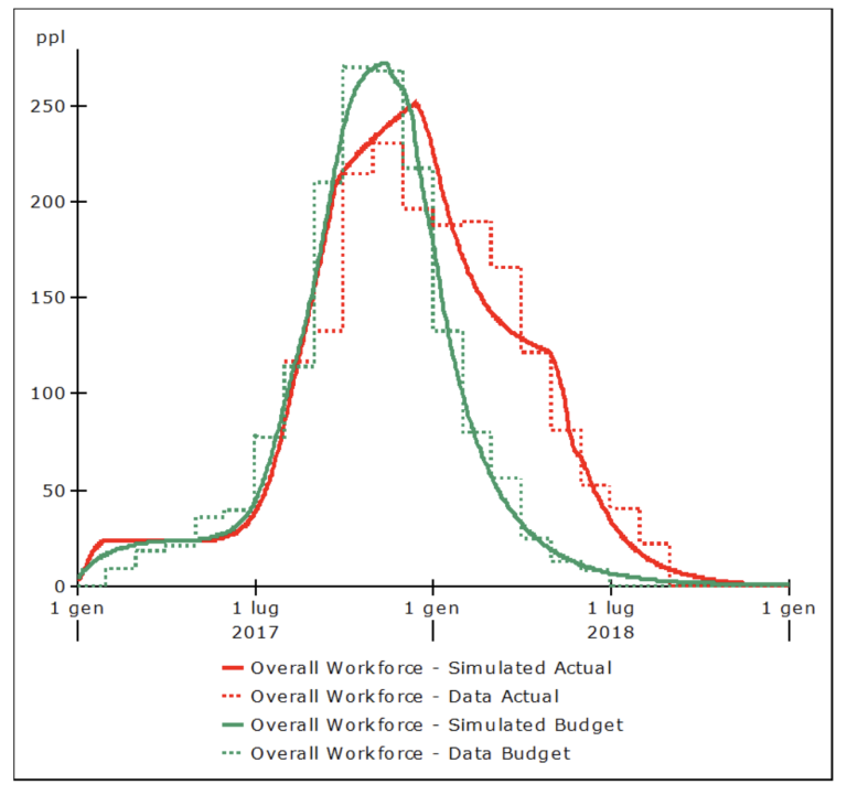
In this way we were able to reproduce ex post, with great accuracy, the resource trends of a project (fig.I) and consequently also the actual progress.

Fig. 1 – RESOURCE TRENDS OBTAINED FROM THE STOCK & FLOW MODEL
Consolidation design
The design of a plant or infrastructure can be schematized as a set of components linked together to perform a certain function.
In the particular case of the design of a thermoelectric power plant in which there are components such as: pumps, exchangers, turbines, steam generators, electric generators, etc., the function of the set of these elements is the generation of electricity from the use of thermal energy.
The design components are characterized by physical data (temperatures, pressures, flow rates, etc..) and geometric data (diameters, lengths, coordinates, etc..) derived from the function required of the component (dimensional criterion). They, however, in addition to being sized appropriately to perform their function, must also allow the whole assembly to function. Thus each component must be connected in the network of components of the design in a congruent manner with the complementary part of the design itself (consistency of interfaces). This involves an iterative process that is typical of the design phase.
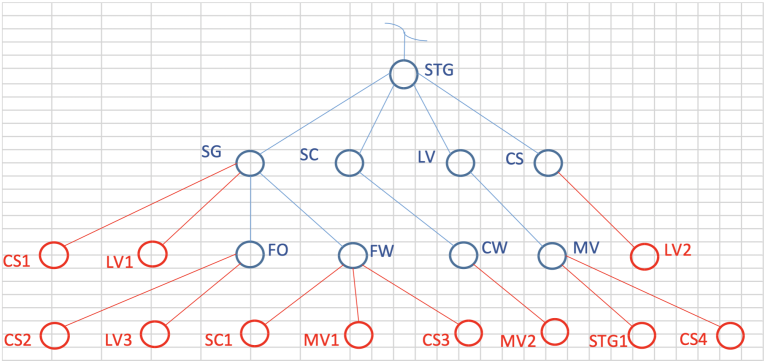
The following figure (Fig. 2) shows a lattice that schematically represents the growth in the number of main components of a thermoelectric plant (blue elements) and the revisions of those components as the lattice grows (red elements).

Fig. 2 – SCHEMATIC OF THE GROWTH OF THE COMPONENTS OF A THERMOELECTRIC PLANT AND THE REVISIONS AS THE GRID ITSELF GROWS
The development of the design lattice from the initial node requires new nodes that are added progressively by successive steps to the existing ones, but it also requires the continuous revisions of the nodes themselves.
Revising the design of an item can be a relatively simple task if relative margins (buffers) and redundancies (spares) have already been provided at the beginning of the project, but if this has not been done, “design reviews” can be triggered that call into question much of what has already been designed.
This iterative design development process can be modeled and can provide useful insights mediated through simulation.
Review of Documentation
The process of preparing, reviewing and approving documents for a project follows the development needs of the project itself, and since the latter is typically an iterative process, the flow of documentation also follows the same pattern.
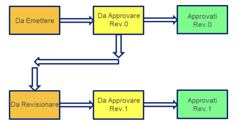
The following figure (fig.3) illustrates the model that reproduces the document approval process under the simplified assumption that only an issuing party, which prepares and issues documents for approval, and a receiving party, which checks the documents by approving or rejecting them with comments. We also assume that the documents do not undergo more than one review before being approved.
Finally, we assume in our model that the resources involved are decreasing as the remaining work decreases.

Fig. 3 – Finally, we assume in our model that the resources involved are decreasing as the remaining work decreases.
Issued documents reduce the backlog of planned documents to be issued with a speed that depends on resources and their productivity.
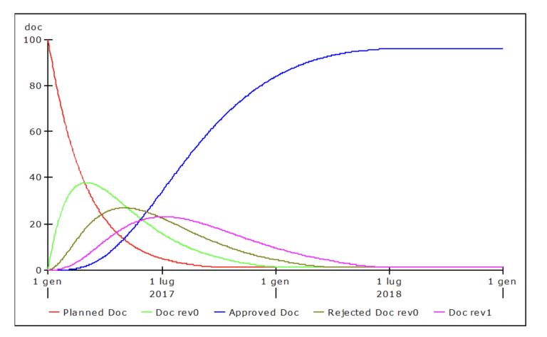
The curve of approved documents (fig.4) grows with delay as a result of the “disposal” of intermediate accumulations. Project planning must take into account this calculable delay with dynamic S&F model.

Fig. 4 – APPROVAL CURVE OF PROJECT DOCUMENTS